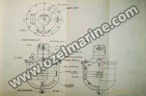
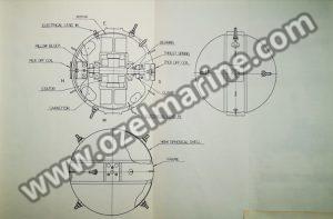
Gyrosphere
As shown at figure, the gyrosphere is the most important element of the master compass and is 108mm in diameter. This contains a 30mm thick gyro rotor having a diameter of 98mm that rotates (approximately 12,000 r.p.m.)on ball bearings installed between the rotor and the rotor shaft. The rotating direction is clockwise when seen from the south side of the gyroscope (where the lead wire is seen coming out of the shaft). A specially superior quality grease is used in lubricating the ball bearings that support the rotor. The rotor is balanced so precisely that almost no vibration is detected to affect its performance. However, if, for some reasons, you fail to adjust the rotor balance effectively, it will cause errors due to rotation related vibrations. Besides, the rotor is so constructed that the position of its center of gravity is not affected by the elasticity of the shaft caused by variations in temperature conditions. The rotor is fixed to the frame by using the pillow block.
The motor used for the gyro rotor represents a 3-phase squirrelcage induction motor. The input power source employs single phase short waveforms which are converted to 3-phase waveforms by the condenser to start the motor.
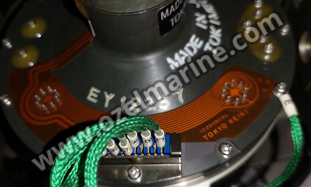
The primary coils of the pick-off device are attached to the north and south sides of the gyrosphere which are then divided by capacitor and energized by the differential voltage. Besides, the input power supply terminals, are installed at the east and west sides of the frame.
The gyrosphere is also used to enclose the motor in a vacuum state by using the frame and two covers. A small amount of helium is, then, injected to dissipate the radiant bent of the motor. When immerged in highly viscous silicon liquid, the center of buoyancy of the gyrosphere coincides with its center of gravity. At that point, the gyrosphere is adjusted in a way that its gravity reaches a level greater than its buoyancy.
In addition, the gyroscope is suspended from the upper end of the container by 2 suspension wires at a position slightly above the center of gravity.
Sensitive Element
As shown at figure, the sensitive element consists of the upper and lower containers housing the highly viscous silicon liquid. A sintered metal alloy plate for regulating the expanding/contracting characteristics of the silicon liquid due to the variations of temperature conditions, is fitted as a cap at the top of the upper container. Then, a tangent screw mechanism is set at the suspension wire mounting locations to check the torsion of the suspension wires. Besides, the upper container is provided with a sensitive level meter to point out the tilt of the rotor. The graduation of the above meter corresponds to two minutes of tilt per one scale.
A semisphere shapped clearance adjusting mechanism is installed at the bottom of the lower container to control errors generated by rolling and pitching of the ship. You can also used this device to move the adjusting mechanism up and down by rotating the shaft so that the clearance between the gyroscope and the said mechanism can be controlled properly.
The sensitive element is set to the mounting ring which is supported by the horizontal axis of the horizontal ring. If required, you can easily remove this sensitive element from the mounting ring.